Balloon Gen 1 Avionics
| Oscar | |
|---|---|
| Part of the HABEES series | |

| |
| Chief Designer | Kirill Safin |
| Technology Line | Balloons Core Avionics |
| Version | Generation I |
| Name | Oscar (the grouch) |
| General | |
| HONEY Standards • Venom Breakout • Fang Breakout • Board Naming | |
| Core Architecture | |
| Gen 1 Architecture • HONEY | |
| Core Avionics | |
| Oscar • Cookie Monster • Elmo • The Count | |
| Core Power | |
| Apple Turnover• Biscuit | |
| Core Peripherals | |
| Medusa • Cobra • Viper • QueenBee • ProtoBee | |
| Core Radio | |
| Macaw | |
| Test & Prototype | |
| QueenBee | |
| Guides | |
| Making a HONEY Board • Using STINGR • Using QueenBee • Making a Prototype | |
| V • E | |
The Balloons Gen 1 Avionics Platform is the first core avionics suite developed by HABEES. Named Oscar, this avionics suite flew on a failed technology demonstration in SSI-39, followed by a successful demonstration in SSI-40. As the first core avionics suite, it set the expectations for features to be included in subsequent revisions.
The full list of features found on Oscar:
- Teensy 3.2 Main MCU
- Five total pressure/temperature sensors, including two BMP280's, two MS5803's, and one MPL3115A2
- Micro SD card data logging
- Real Time Clock with backup battery
- Thermocouple for external temperature sensing
- uBlox NEO-6M GPS
- 6 custom-use MOSFET's
- Current sensing on two MOSFET's
- Indicator LED's for flight critical states
- Battery Protection (OV/UV/OC)
- 5V Battery Boost
- RockBlock Satellite Communications
- Pinouts for I2C, SPI, Power
Design
Oscar was designed around the concept of meeting core HAB flight requirements -- nothing more and nothing less. Thus, the key elements of a HAB flight were considered to be: internal temperature, altitude, external temperature, location, data logging, cutdown/heating, satellite communications, and state indication.
A total of five pressure/temperature sensors were selected, from three different varieties. The inspiration for this was robust fusion across slightly different sensors with various resolutions and accuracies. Further, ValBal maintained a history of fusing multiple pressure sensors, and this was used as inspiration for core avionics.
A NEO-6M GPS was chosen as the primary GPS unit due to its low cost ($20 compared to previously used GPS's such as the Adafruit GPS which cost $50), proven reliability, and attachable antenna.
An IC2 Multiplexer (The MCP23017) was chosen to control both the custom-use MOSFET's and indicator LED's so as to not utilize capable Teensy pinouts for mundane purposes. A total of eight indicator LED's were driven by the multiplexer, as well as all six MOSFET's. At the time of brainstorming, the suggested LED-indicated states included the following: Pressure In Range, Temperature In Range, SD Good (logging), GPS Good (has lock), RB Good (transmitting), Battery Good (in voltage), Current Good (in range), Power Good (protector not enabled), and heartbeat BLINK.
A thermocouple was included on Oscar as "outside temperature" began to be considered critical flight information. A thermocouple had only been flown in the Core Avionics POC before, but had been considered of reasonable utility and having numerous applications for further research projects and avionics expansions.
An RTC was included to be able to log data with timestamps to allow post-analysis simpler and reduce burden on "syncing" up times from the data log to the launch. The SD data logging accompanies all balloon flights for logging of core data.
The RockBlock was included in the core avionics as a vital part of any avionics suite -- the ability to both transmit and receive data being a fundamental part of any suite.
The power circuits, designed by Sasha Maldonado, provided for battery protection and 5V boost capability. The battery pack contained no on-board BMS -- all relevant circuits were integrated into the avionics.
Pinouts were provided for I2C, SPI, as well as VIN, 3.3V, 5V, and GND to allow for the extension of the avionics with additional sensors or other auxiliary features.
Schematics
A full gallery of all Oscar schematics can be seen below. This section discusses each sub-circuit separately.
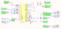
Top Sheet

The top sheet displays the overarching hierarchy of the avionics board. Only perimeter Teensy pins were utilized, hence pins 24-33 and A10-A14 are NC. The GPS was connected to Hardware Serial 1 over pins 0/1. Pin 2 was driven low when SD card was detected (output of the Micro SD sheet). Pins 3-5 were not utilized. Pins 6-9 were used for RockBlock operation, although NETAV & SLEEP were not used for actual operation, and may be discarded in the future. Pins 10-13 were used to define the SPI Bus, and pin 10 was used as the Micro SD chip select. As seen in the bottom left, pinouts were supplied for I2C and SPI. VIN was supplied with +5V from the boost circuit. Two decoupling caps for +3.3 and +5 were sourced local to the MCU. Pins 22-20 were defined as chip selects for the thermocouple and BMP 280's (22 for thermocouple, 21/20 for BMP280). Pins 19/18 defined the I2C bus. The I2C bus had five total devices: Two MS5803's, One MPL3115A2, One MCP23017 multiplexer, and one RTC IC. Pin 16 connected to the battery protector (LTC4218) power good indicator. Pins 15 and 14 were used for current monitor (via 4218) and battery voltage detection.
Thermocouple
The thermocouple used the MAX3115K amplifier for thermocouple amplification and a K-type thermocouple. D11/D12, as well as R28/R27 were both included in the schematic and later discarded in the physical PCB. D11/D12 were shorted, while R28/R27 were open-circuited. These were included from the Adafruit breakout schematic, but exist purely for the purpose of shifty logic shifting, which was not necessary with a 3.3V MCU like the Teensy. Polarized Decoupling caps (which needn't be polarized) were included. A 1uF filter cap was placed between two signal conditioning ferrite beads (1kHz), which led to a 2 circuit Microfit connector.
Sensors
Both BMP280 sensors utilized SPI. A 100nF decoupling cap was provided for both. Both MS5803 sensors utilized I2C; addresses were set to 0x76 and 0x77 using the CSB address selection pin. 100nF decoupling caps were provided for both. The MPL3115A2 similarly utilized I2C -- no decoupling cap is provided; rather, a 1uF capacitor is provided to the CAP pin. 10 kOhm pullups are provided for the I2C bus.
RTC
A DS1307 RTC IC is utilized for the real-time clock. The Teensy 3.2 internal RTC is avoided due to past difficulties/problems. The DS1307 is powered by 5V (no 3.3V variety exists). A 32.768kHz 12.5pF time-keeping crystal X1 is used for the RTC, and a keystone 12mm coin cell holder provides backup power for the RTC. A 100 nF decoupling cap is provided.

RockBlock
The RockBlock uses a 2x3 vertical Molex microfit connector. It is provided +5V, GND, Serial TX/RX lines, as well as connections for the SLEEP & NETAV pins, which are not utilized.
Battery Protector
The LTC4218 multi-function IC is used for battery pack protection. A resistive network in the order of VBAT->18k->6.2k->91.k->GND is implemented to specify an overvoltage threshold of 4.52V and an undervoltage threshold of 2.3V. A current limit of 5 amps is implemented utilizing R23/RSENSE as defined by the 4218 data sheet. A shut-off FET Q7 is implemented to turn off the avionics in fault cases. A PG state is provided to the MCU.
Pinouts
Pinouts are provided for SCL, SDA, MOSI, MISO, SCLK, GND, +3.3, +5, and +VIN. I2C bus pinouts are given 6 pins, SPI bus pinouts are given 4 pins, and power pinouts are given 12 pins.
Multiplexer
The MCP23017 is used as a 16 I/O I2C multiplexer. A2/A1/A0 are grounded for default address selection. Reset is pulled high to disable reset functionality. Pins 0 - 7 are used to drive indicator LEDs, while pins 8 - 13 are used for binary operation of custom FETs.
Micro SD
The Micro SD connector is connected to the SPI bus and provided power. A card detect state (pulled low when detected) is connected to the MCU.
LEDs
Eight LED's are controlled by the multiplexer, with 220 ohm current limiting resistors. The LED's are green.
GPS
A 4 pin precidip socket is used to connect the external NEO-6M GPS breakout. Notably, The TX & RX lines are incorrect and should be swapped.
FETs
FET1 & FET2 include an INA169 I2C current monitor (which is later removed prior to flight because it was not being used and to remove possible I2C bus problems). Current monitors have addresses selected via pins A0/A1. An 0.1 ohm current sense resistor is used to calibrate the INA169 according to the data sheet. 2 pin vertical Molex Mirofit connectors are used for the custom FETs. All FETs are powered from raw battery voltage for high current applications. FET3-FET6 do not use current monitors. Notably, all six FET's have an incorrectly connected LED which does not function on the actual PCB.
5V Boost
An LTC3428 is used for the 5V boost circuit. All relevant passives are determined from the LTC3428 datasheet. A two circuit molex microfit connector is used for the battery input.
Top Sheet 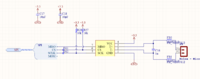
Thermocouple Sheet 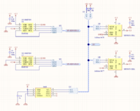
Sensors Sheet 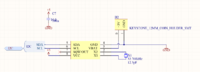
RTC Sheet 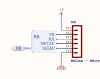
RockBlock Sheet 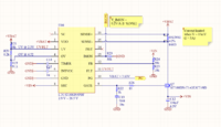
Battery Protector Sheet 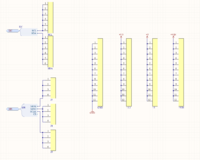
Pinouts Sheet 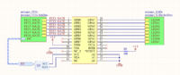
Multiplexer Sheet 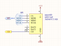
MicroSD Sheet 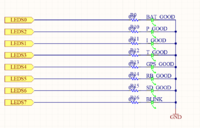
LEDs Sheet 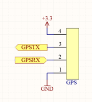
GPS Sheet 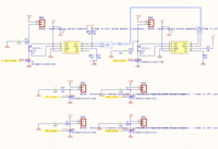
FETs Sheet 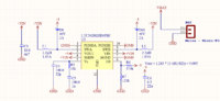
5V Boost Sheet


PCB Design

The PCB layout for Oscar can be seen on the right. Oscar was notable for its novel shape -- a 3/4 hexagon, designed to fit perfectly in a Gen 1 HABHIVE container and allow some space for routing wiring and positioning a RB/battery pack vertically.
Oscar also notably has battery protection and boost circuits locally, on the bottom right hand side. This is the first and last instance that a Core Avionics suite contains on-board battery protection/boosting. Subsequent power circuits are relocated to an external BMS. Oscar is also notable for very low part density -- this is in part due to its large size, which, although more large than necessary, is defined as such for mechanical purposes. Oscar also features surface mount Molex Microfit connectors, which are replaced in subsequent lines of avionics platforms in exchange for smaller footprint through-hole varieties. Oscar is the first and only avionics suite to only use the perimeter pins of the Teensy 3.2 -- subsequent avionics all use the additional underbelly pins.
Oscar has three mounting holes, designed for #8 bolts, for mechanical integration into HABHIVE.
Milestones
Oscar is the first-ever PCB developed for the Balloons Core Avionics Suite. It is also one of the most feature rich and modular avionics systems produced within SSI at the time of its creation. Every system on Oscar is functional and flight-proven -- the only subsystem that was not proven was the FET current sensing, which was removed.
Problems
Oscar, as the first in the line of avionics suites, was riddled with problems in its production, design, execution, and testing.
Key problems included:
- Initial reflow of Oscar resulted in many shorts, most notably on the MCP23017 and LTC4218.
- Very small grid spacing in Altium resulted in multiple pins on the I2C multiplexer being unconnected to anything. All three address selection pins were short-soldered together, and greenwired to the backup battery ground pad.
- Vigorous whicking removed a trace & via leading to FET 1, resulting in FET 1 being unusable.
- Poor reflow of pressure sensors resulted in the removal and subsequent re-soldering of all pressure sensors. Only one of the two BMP280's and one of the MS5803's is functioning at final flight time. The MPL3115A2 is functional for some period of time, and non-functional by time of flight.
- Improper design of FET LED circuit.
- The GPS breakout TX/RX lines are swapped; they are later swapped on the breakout itself, to allow for the PCB to remain unmodified.
- Despite having SPI pinouts, there are no chip select pinouts.
- The thermocouple is connected backwards, the ferrite beads were of the improper frequency rating, and the diodes had to be removed.
Flights
SSI-39

SSI-39, the inaugural flight of Oscar, was a flight plagued with unfortunate mistakes, and some poor decision making. Flight software for Oscar was completed approximately 4 hours before departure from campus, fully functional. En route to launch site, additional components were added, including ascent rate calculation, as well as GPS flight mode and a few other features.
At launch site, extensive debugging and checking took place to verify the system. GPS lock was seldom obtained initially, but was later regained with high frequency. RockBlock communication was very sparse, often losing lock and communicating on average every 15-20 minutes rather than the programmed 2 minute interval. Debugging, configuration, and testing took place on-site until 1 pm -- two hours past the 11 am expected launch time. At this point, the system was performing nominally outside of habhive, but, upon insertion, worked sporadically, until the flight software terminated randomly. At one point, it was determined that the time was getting late and the payload must be launched. A communication was received, and it was determined that the payload was ready for flight. After release, no more communications were received.
Upon return to campus, root cause of failure was analyzed. The problem lied in the GPS antenna being loose -- contact with pressure sensor housing of the BMP280 or MPL3115A2 caused flight software to crash. The flight provided no data logs, and no communications.
Aside from the antenna problem, the system was nominal.
SSI-40
SSI-40, taking place shortly after SSI-39, was an exact re-flight of Oscar, with the modification of having the GPS antenna taped to a habhive wall. The system performed nominally from prep to launch and throughout the entire flight. Communications were frequent, coming in often 30 seconds apart. The payload successfully recorded and transmitted flight critical parameters for the entire duration of the flight, including internal and external temperatures, altitude, ascent rate, power state, and more. A successful cutdown was also triggered at 25 km using a custom FET and nichrome wire. A heater was included but did not activate during the flight.
The payload was recovered floating atop algae in an irrigation canal. All flight electronics remained in nominal state at time of recovery. The Micro SD card contained thorough data from throughout the entire flight.