Balloons Gen 5 Avionics
| Kermit | |
|---|---|
| Part of the HABEES series | |

| |
| Chief Designer | Vinh Nguyen |
| Technology Line | Balloons Core Avionics |
| Version | Generation V |
| Name | Kermit |
| General | |
| HONEY Standards • Venom Breakout • Fang Breakout • Board Naming | |
| Core Architecture | |
| Gen 1 Architecture • HONEY | |
| Core Avionics | |
| Oscar • Cookie Monster • Elmo • The Count | |
| Core Power | |
| Apple Turnover• Biscuit | |
| Core Peripherals | |
| Medusa • Cobra • Viper • QueenBee • ProtoBee | |
| Core Radio | |
| Macaw | |
| Test & Prototype | |
| QueenBee | |
| Guides | |
| Making a HONEY Board • Using STINGR • Using QueenBee • Making a Prototype | |
| V • E | |
Kermit is the fifth revision of the HABEES Standard Avionics Platform. It implements most of the functionality that exists in Gen 4 rev 2 Avionics, but the architecture of the boards has been changed, and functionality removed to reduce the complexity of implementation and application of the flight stack.
Kermit provides the following flight critical systems features:
- A Teensy 3.6 embedded Microcontroller
- A ublox-M8Q GNSS (GPS/GLONASS/Beidou/Galileo) receiver with embedded patch antenna
- MicroSD data logging
- A thermocouple for external temperature sensing
- Two BMP280 pressure/temperature sensors
- A PWM-operated cutdown FET
- An inboard heater
- Power, CAN, and data bus connectors
- 8 RGB indicator LED's about various system states
- A power-selector to enable 5V operation from BMS or USB
- CAN Transceiver for use with the HONEY CAN bus
- Additional bypass capacitors
- Current sensors for GPS and Cutdown
Notable differences from the previous generation include:
- SiLabs 4463 Radio, the same used as Valbal v9.
This provides a higher bandwidth data link for use by expansion boards so that future applications need only generate data and send it to main avionics.
- Connector for Iridium RockBlock module
An embedded module proved to be too difficult to implement in the previous revision, while not providing significant benefit over using the out-of-the-box RockBlock module + connector alternative.
Development
Given the difficulty that was experienced in assembling and testing the previous generation of standard avionics, the current generation was built with the primary goal in mind of reducing the complexity and producing a system whose core functionality is easier to realize and least liable to fail after assembly (given that most likely avionics must be manually assembled and debugged).
Several changes were made from Rev 4.2 in order to reduce the complexity:
- The data bus was split into two, and the number of pins broken out was reduced only to the number of GPIOs free after all avionics systems, simplifying routing and reducing the number of pins.
- Abandoning an embedded RockBlock and its dedicated power circuitry, which required a large footprint and ultimately incredibly dense packing and clever routing to accommodate the rest of the system.
- Removing auxiliary heater FETs
- Removing some current sensors, because power consumption data for its own sake is not considered a priority for standard-profile launches
- Removing the second, excessive CAN bus
- Removing the IMU
- Removing watchdog circuitry, because historical standard-profile launches have not shown frequent anomalies that would make a watchdog critical, let alone problems that would be solved by the watchdog as it was implemented in Gen 4.2
- Forgoing power select circuitry for a simple switch
Testing
The boards are set to be assembled and tested during the fall of the 2018/19 academic year, with a first launch planned for Winter 2019.
Issues
The inclusion of the SiLabs radio may be adding unnecessary complexity that is best deferred to an expansion board.
PCB Layout
Gen 5 Avionics remains a 4-layer board, compliant with Gen 2 Architecture. All signals were routed on the top and bottom layers, while only the heater trace went beyond those two layers. While it may be possible to route the heater trace on the top and bottom layer, it will be much more difficult, if impossible, to apply the traces directly to the components which require heat, such as the GPS and MCU.
Schematics
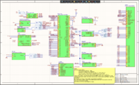
Top Sheet 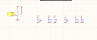
Bypass Capacitors 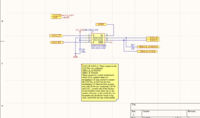
CAN 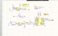
GPS 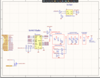
Radio 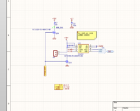
Cutdown 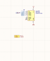
SD Card 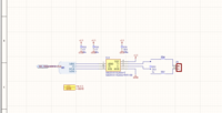
External Temperature Sensing 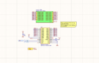
Multiplexer for LEDS 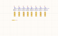
Status LEDs 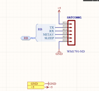
RockBlock Connector 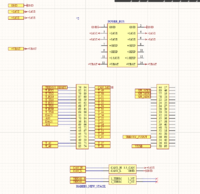
Connections to Stackbus 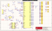
Teensy 3.6 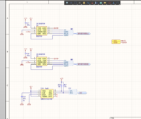
Pressure Sensors/center>


