Difference between revisions of "Medusa"
| Line 44: | Line 44: | ||
File:Medusa_pcb.PNG | <center> PCB Layout </center> | File:Medusa_pcb.PNG | <center> PCB Layout </center> | ||
</gallery> | </gallery> | ||
| + | |||
| + | == Pinouts == | ||
| + | |||
| + | {| class="wikitable" | ||
| + | | Pin | ||
| + | | Slot 1 | ||
| + | | Slot 2 | ||
| + | | Slot 3 | ||
| + | | Slot 4 | ||
| + | | Slot 5 | ||
| + | |- | ||
| + | | 1 | ||
| + | | +5V | ||
| + | | +5V | ||
| + | | +5V | ||
| + | | +5V | ||
| + | | +5V | ||
| + | |- | ||
| + | | 2 | ||
| + | | +5V | ||
| + | | +5V | ||
| + | | +5V | ||
| + | | +5V | ||
| + | | +5V | ||
| + | |- | ||
| + | | 3 | ||
| + | | +3.3V | ||
| + | | +3.3V | ||
| + | | +3.3V | ||
| + | | +3.3V | ||
| + | | +3.3V | ||
| + | |- | ||
| + | | 4 | ||
| + | | +3.3V | ||
| + | | +3.3V | ||
| + | | +3.3V | ||
| + | | +3.3V | ||
| + | | +3.3V | ||
| + | |- | ||
| + | | 5 | ||
| + | | +VBAT | ||
| + | | +VBAT | ||
| + | | +VBAT | ||
| + | | +VBAT | ||
| + | | +VBAT | ||
| + | |- | ||
| + | | 6 | ||
| + | | +VBAT | ||
| + | | +VBAT | ||
| + | | +VBAT | ||
| + | | +VBAT | ||
| + | | +VBAT | ||
| + | |- | ||
| + | | 7 | ||
| + | | GND | ||
| + | | GND | ||
| + | | GND | ||
| + | | GND | ||
| + | | GND | ||
| + | |- | ||
| + | | 8 | ||
| + | | GND | ||
| + | | GND | ||
| + | | GND | ||
| + | | GND | ||
| + | | GND | ||
| + | |- | ||
| + | | 9 | ||
| + | | RX1 | ||
| + | | RX2 | ||
| + | | RX3 | ||
| + | | A12 (SSE) | ||
| + | | A11 (SSE) | ||
| + | |- | ||
| + | | 10 | ||
| + | | TX1 | ||
| + | | TX2 | ||
| + | | TX3 | ||
| + | | A1 (SSE) | ||
| + | | A2 (SSE) | ||
| + | |- | ||
| + | | 11 | ||
| + | | MOSI | ||
| + | | MOSI | ||
| + | | MOSI | ||
| + | | MOSI | ||
| + | | MOSI | ||
| + | |- | ||
| + | | 12 | ||
| + | | MISO | ||
| + | | MISO | ||
| + | | MISO | ||
| + | | MISO | ||
| + | | MISO | ||
| + | |- | ||
| + | | 13 | ||
| + | | SCLK | ||
| + | | SCLK | ||
| + | | SCLK | ||
| + | | SCLK | ||
| + | | SCLK | ||
| + | |- | ||
| + | | 14 | ||
| + | | 21 (CSA) | ||
| + | | 20 (CSB) | ||
| + | | 24 (CSC) | ||
| + | | 33 (CSD) | ||
| + | | 26 (CSE) | ||
| + | |- | ||
| + | | 15 | ||
| + | | SCL | ||
| + | | SCL | ||
| + | | SCL | ||
| + | | SCL | ||
| + | | SCL | ||
| + | |- | ||
| + | | 16 | ||
| + | | SDA | ||
| + | | SDA | ||
| + | | SDA | ||
| + | | SDA | ||
| + | | SDA | ||
| + | |- | ||
| + | | 17 | ||
| + | | NC | ||
| + | | NC | ||
| + | | NC | ||
| + | | 5 (PWM1) | ||
| + | | 5 (PWM1) | ||
| + | |- | ||
| + | | 18 | ||
| + | | NC | ||
| + | | NC | ||
| + | | NC | ||
| + | | 6 (PWM2) | ||
| + | | 6 (PWM2) | ||
| + | |- | ||
| + | | 19 | ||
| + | | 23 (PWM3) | ||
| + | | 5 (PWM1) | ||
| + | | 32 (PWM5) | ||
| + | | 23 (PWM3) | ||
| + | | 23 (PWM3) | ||
| + | |- | ||
| + | | 20 | ||
| + | | 22 (PWM4) | ||
| + | | 6 (PWM2) | ||
| + | | 25 (PWM6) | ||
| + | | 22 (PWM4) | ||
| + | | 22 (PWM4) | ||
| + | |- | ||
| + | | 21 | ||
| + | | NC | ||
| + | | NC | ||
| + | | NC | ||
| + | | 16 (A1) | ||
| + | | 16 (A1) | ||
| + | |- | ||
| + | | 22 | ||
| + | | NC | ||
| + | | NC | ||
| + | | NC | ||
| + | | 17 (A2) | ||
| + | | 17 (A2) | ||
| + | |- | ||
| + | | 23 | ||
| + | | NC | ||
| + | | NC | ||
| + | | NC | ||
| + | | A10 (A3) | ||
| + | | A10 (A3) | ||
| + | |- | ||
| + | | 24 | ||
| + | | NC | ||
| + | | NC | ||
| + | | NC | ||
| + | | A11 (A4) | ||
| + | | A11 (A4) | ||
| + | |- | ||
| + | | 25 | ||
| + | | A12 (A5) | ||
| + | | 16 (A1) | ||
| + | | 29 (A9) | ||
| + | | A12 (A5) | ||
| + | | A12 (A5) | ||
| + | |- | ||
| + | | 26 | ||
| + | | A13 (A6) | ||
| + | | 17 (A2) | ||
| + | | 28 (A10) | ||
| + | | A13 (A6) | ||
| + | | A13 (A6) | ||
| + | |- | ||
| + | | 27 | ||
| + | | A14 (A7) | ||
| + | | A10 (A3) | ||
| + | | 27 (A11) | ||
| + | | A14 (A7) | ||
| + | | A14 (A7) | ||
| + | |- | ||
| + | | 28 | ||
| + | | 30 (A8) | ||
| + | | A11 (A4) | ||
| + | | 14 (A12) | ||
| + | | 30 (A8) | ||
| + | | 30 (A8) | ||
| + | |- | ||
| + | | 29 | ||
| + | | NC | ||
| + | | NC | ||
| + | | NC | ||
| + | | 29 (A9) | ||
| + | | 29 (A9) | ||
| + | |- | ||
| + | | 30 | ||
| + | | NC | ||
| + | | NC | ||
| + | | NC | ||
| + | | 28 (A10) | ||
| + | | 28 (A10) | ||
| + | |- | ||
| + | | 31 | ||
| + | | NC | ||
| + | | NC | ||
| + | | NC | ||
| + | | 27 (A11) | ||
| + | | 27 (A11) | ||
| + | |- | ||
| + | | 32 | ||
| + | | NC | ||
| + | | NC | ||
| + | | NC | ||
| + | | 14 (A12) | ||
| + | | 14 (A12) | ||
| + | |- | ||
| + | | 33 | ||
| + | | +3.3V | ||
| + | | +3.3V | ||
| + | | +3.3V | ||
| + | | +3.3V | ||
| + | | +3.3V | ||
| + | |- | ||
| + | | 34 | ||
| + | | CD | ||
| + | | CD | ||
| + | | CD | ||
| + | | CD | ||
| + | | CD | ||
| + | |- | ||
| + | | 35 | ||
| + | | +5V | ||
| + | | +5V | ||
| + | | +5V | ||
| + | | +5V | ||
| + | | +5V | ||
| + | |- | ||
| + | | 36 | ||
| + | | +5V | ||
| + | | +5V | ||
| + | | +5V | ||
| + | | +5V | ||
| + | | +5V | ||
| + | |- | ||
| + | | 37 | ||
| + | | GND | ||
| + | | GND | ||
| + | | GND | ||
| + | | GND | ||
| + | | GND | ||
| + | |- | ||
| + | | 38 | ||
| + | | GND | ||
| + | | GND | ||
| + | | GND | ||
| + | | GND | ||
| + | | GND | ||
| + | |} | ||
Revision as of 17:10, 27 August 2016
Medusa is a HABEES developed expansion board for the Balloons Core Avionics. Medusa is designed to accept five 40-pin edge-cards to support a variety of add-on functionalities to enhance the capabilities of the Core Avionics suite.
Medusa consists of five board-locking 80 pin edge-card slots, a micro SD for data logging, a Teensy 3.2 MCU, power input, and a CAN transceiver.
Medusa functions by providing appropriate power & signal buses to all card slots, allowing external boards to implement I2C, SPI, UART, Analog, PWM functionalities to perform meaningful operations. Medusa receives commands from the Core Avionics over CAN, and is able to transmit data back to the Core Avionics along CAN as well. It is capable of logging all raw readings from installed cards locally, and transmitting only necessary or otherwise processed data back to the avionics.
Design
Medusa is partitioned into five total slots -- three of which are standard slots, and two of which are god slots. Standard slots partition various pins to reduce or eliminate any conflicts among simultaneously installed cards. God Slots provide access to all Teensy pins that are broken out to the slots.
Each card slot is provided: +5V, +3.3V, +VBAT, GND, I2C, SPI with a unique chip select pin, and a card-detect LED.
Each of the standard slots partition a subset of pins and protocols. Each of the standard slots is provided a Hardware Serial line; Slot 1 utilizes Hardware Serial 1, Slot 2 uses Hardware Serial 2, and so on. They also partition a subset of the PWM and ANALOG pins broken out by the Teensy. All Standard slots have two PWM pins, located on pins 37/38 and 39/40. Each standard slot also has four ANALOG pins, located on pins 53/54, 55/56, 57/58, and 59/60.
Slot 1 uses PWM 3/4 and ANALOG 5/6/7/8, Slot 2 uses PWM 1/2 and ANALOG 1/2/3/4, while Slot 3 uses PWM 5/6 and ANALOG 9/10/11/12. This is enumerated on the breakout manifest found on the PCB silkscreen.
The God Slots, however, break out all of these pins. That is, the God Slots have access to PWM 1-6 and ANALOG 1-12. The God Slots should only be used under two conditions: one is the necessity for a large number of ANALOG or PWM pins (more than a standard slot provides), and two being the need for four total cards, with the standard three slots being already taken up. In any case, it is critical for slots to be chosen wisely to avoid conflicts between cards.
God Slots also have the option of using Serial -- however, they utilize Software Serial, and only if enabled using the SS jumpers found on the left of each of the slots. Slot 4 uses Analog pins 1 & 12 for Serial, while Slot 5 uses Analog pins 2 & 11.
All cards should include a trace from pin 71 to pin 72 to enable the on-board medusa card-detect LED.
Schematics
All Medusa Schematics, as well as the PCB Layout, can be found below.
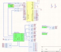
Top Sheet 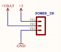
Power Connector 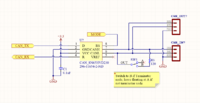
CAN Bus 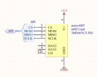
Micro SD 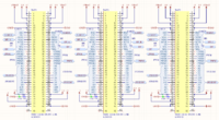
Standard Slots 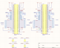
God Slots 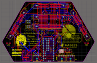
PCB Layout


Pinouts
| Pin | Slot 1 | Slot 2 | Slot 3 | Slot 4 | Slot 5 |
| 1 | +5V | +5V | +5V | +5V | +5V |
| 2 | +5V | +5V | +5V | +5V | +5V |
| 3 | +3.3V | +3.3V | +3.3V | +3.3V | +3.3V |
| 4 | +3.3V | +3.3V | +3.3V | +3.3V | +3.3V |
| 5 | +VBAT | +VBAT | +VBAT | +VBAT | +VBAT |
| 6 | +VBAT | +VBAT | +VBAT | +VBAT | +VBAT |
| 7 | GND | GND | GND | GND | GND |
| 8 | GND | GND | GND | GND | GND |
| 9 | RX1 | RX2 | RX3 | A12 (SSE) | A11 (SSE) |
| 10 | TX1 | TX2 | TX3 | A1 (SSE) | A2 (SSE) |
| 11 | MOSI | MOSI | MOSI | MOSI | MOSI |
| 12 | MISO | MISO | MISO | MISO | MISO |
| 13 | SCLK | SCLK | SCLK | SCLK | SCLK |
| 14 | 21 (CSA) | 20 (CSB) | 24 (CSC) | 33 (CSD) | 26 (CSE) |
| 15 | SCL | SCL | SCL | SCL | SCL |
| 16 | SDA | SDA | SDA | SDA | SDA |
| 17 | NC | NC | NC | 5 (PWM1) | 5 (PWM1) |
| 18 | NC | NC | NC | 6 (PWM2) | 6 (PWM2) |
| 19 | 23 (PWM3) | 5 (PWM1) | 32 (PWM5) | 23 (PWM3) | 23 (PWM3) |
| 20 | 22 (PWM4) | 6 (PWM2) | 25 (PWM6) | 22 (PWM4) | 22 (PWM4) |
| 21 | NC | NC | NC | 16 (A1) | 16 (A1) |
| 22 | NC | NC | NC | 17 (A2) | 17 (A2) |
| 23 | NC | NC | NC | A10 (A3) | A10 (A3) |
| 24 | NC | NC | NC | A11 (A4) | A11 (A4) |
| 25 | A12 (A5) | 16 (A1) | 29 (A9) | A12 (A5) | A12 (A5) |
| 26 | A13 (A6) | 17 (A2) | 28 (A10) | A13 (A6) | A13 (A6) |
| 27 | A14 (A7) | A10 (A3) | 27 (A11) | A14 (A7) | A14 (A7) |
| 28 | 30 (A8) | A11 (A4) | 14 (A12) | 30 (A8) | 30 (A8) |
| 29 | NC | NC | NC | 29 (A9) | 29 (A9) |
| 30 | NC | NC | NC | 28 (A10) | 28 (A10) |
| 31 | NC | NC | NC | 27 (A11) | 27 (A11) |
| 32 | NC | NC | NC | 14 (A12) | 14 (A12) |
| 33 | +3.3V | +3.3V | +3.3V | +3.3V | +3.3V |
| 34 | CD | CD | CD | CD | CD |
| 35 | +5V | +5V | +5V | +5V | +5V |
| 36 | +5V | +5V | +5V | +5V | +5V |
| 37 | GND | GND | GND | GND | GND |
| 38 | GND | GND | GND | GND | GND |