Balloons Gen 1 Radio
| Macaw | |
|---|---|
| Part of the HONEY Architecture series & the HABEES series | |
| Chief Designer | Vinh Nguyen |
| Technology Line | Balloons Core Radio |
| Version | Generation I |
| Name | Macaw |
| General | |
| HONEY Standards • Venom Breakout • Fang Breakout • Board Naming | |
| Core Software | |
| STINGR | |
| Core Avionics | |
| The Count | |
| Core Power | |
| Biscuit | |
| Core Peripherals | |
| Cobra • Viper • ProtoBee | |
| Core Radio | |
| Macaw | |
| Test & Prototype | |
| QueenBee | |
| Guides | |
| Making a HONEY Board • Using STINGR • Using QueenBee • Making a Prototype | |
| V • E | |
Macaw is the first generation of a VHF/UHF transmit/receive board for Balloons Core Avionics. The purpose of the radio board is to provide an alternate means of transmitting payload vitals to the ground, in addition to RockBlock (which requires buying credits to transmit data). In addition, the radio board provides a much higher data rate than Iridium, which can be used to transmit payload vitals more often, and larger data (such as images or video).
Design
Macaw has three DORJI radios, which can be either DRA818Vs (which can transmit from 134MHz to 174MHz in the Very High Frequency(VHF) Band) or DRA818Us (which can transmit from 400-470MHz in the Ultra High Frequency (UHF) Band). Each radio also has a current sensor to monitor the amount of current being drawn from that radio. In Macaw all functionalities of the DORJI radios are supported, which means that any of the radios can be transmit or receive radios, and VHF or UHF radios, although one is designated as the APRS radio (Automatic Packet Reporting System), and the other two are designated as VHF Transmit and VHF Receive. The APRS radio is responsible for transmitting the payload vitals to the ground, while the other two are reserved for higher data-rate applications; however, in the board the hardware for each radio is identical and any VHF radio can transmit or receive any data.
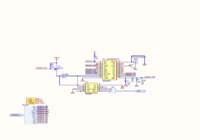
Schematics
-
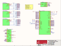
Top Sheet -
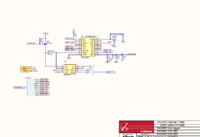
Radio 1/APRS -
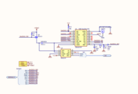
Radio 2/RX -
Radio 3/TX -
Stackbus Connections -
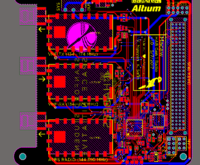
PCB Layout -
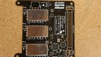
Assembled


Pinout
-APRS = Radio 1; Bottom
-VHFRX = Radio 2; Middle
-VHFTX = Radio 3; Top
Serial Ports: The communication interface between the radio and the microcontroller; used to set settings (ie transmit frequency). RX here is in the frame of the Teensy (MCU RX; radio TX).
| Pin | APRS | VHFRX | VHFTX |
| RX | 7(RX3) | 9 | 0 |
| TX | 8 (TX3) | 10 | 1 |
MIC(Microphone): The signal input to the radio transmitter.
| Pin | APRS | VHFRX | VHFTX |
| DAC/A14 | 22/A8 | 32 |
PTT (Push-To-Talk): The signal which enables or disables transmission
| Pin | APRS | VHFRX | VHFTX |
| 6 | 13 | 25 |
AF_OUT (Audio Out): The output of the radio receiver.
| Pin | APRS | VHFRX | VHFTX |
| 14/A0 | 17/A3 | 28/A17 |
SQ:(Squelch): Signal for setting the squelch level (threshold for suppressing noise in received signals)
| Pin | APRS | VHFRX | VHFTX |
| 5 | 12 | 16/A2 |
PD/SLP (Sleep): Signal for setting the radio to low power mode
| Pin | APRS | VHFRX | VHFTX |
| 20/A6 | 23/A9 | 15/A1 |
RFPWR (RF Power): Signal for setting the radio to .5W output power or 1W output power
| Pin | APRS | VHFRX | VHFTX |
| 21/A7 | 19/A5 | 27/A16 |
EN (Enable): Signal for driving a FET switch to power or unpower each radio (radio is powered if this is LOW)
| Pin | APRS | VHFRX | VHFTX |
| 2 | 11 | 18/A4 |
Other System Flags
LOW PWR (Flag from Main Avionics for asserting Low Power Mode)- 24
System Ready (Flag from Main Avionics for enabling startup) - A10
F3- A11
F4- A12
F5- A13
I2C
SCL - 29/A18
SDA - 30/A19
CHIRP (Serial Communication with Main Avionics). Uses the alternate pins for HWSerial 2 on the Teensy 3.2. Radio 2 Serial will be disabled during use.
RX- 26/A15 (RX2 Alt)
TX- 31/A20 (TX2 Alt)
Issues and Future Design Ideas
• Number and Kind of Radios
One issue with having three VHF radios on one board is the potential for one to interfere with the others if the transmit and receive frequencies are too near one another (crosstalk). A filter between the antenna and radio could solve this, however it requires additional space and components. If interference is significant then a receiving radio would not be able to receive while another is transmitting. In effect this would be no different than having one radio operating half-duplex; components, space, and pins could be saved by removing one radio entirely; the second radio could be changed to UHF. Additional pins and board space allows for more interfacing with the main avionics and other functionality, such as data logging or image/video recording.